Parte 2 Corriente NORD STREAM – Varias vías paralelas hacia el éxito o fracaso?
Los Proyectos de la Corriente Nord Stream 1 & 2 son tremendos logros de la ingeniería. En un Previo del Mes anterior, hemos discutido los aspectos técnicos del Diagrama de Fase, y su fase densa correspondiente, la Hidráulica, Selección de Diámetro, Espesor de la chapa del oleoducto, perfil de la gradiente de presión, y capacidad de transmisión de...
View Article
Part 2: Nord Stream Pipelines – Multiple Parallel Paths to Success or Failure?
April 28, 2022
|
Tip of the Month
The Nord Stream 1 & 2 Subsea Pipeline Projects are a tremendous feat of engineering. In a previous Tip of the Month, we discussed the technical aspects of the Phase Envelope, Hydraulics, Diameter selection, Pipe wall thickness, pressure gradient profile, and flowrate for these multiple parallel pipelines.
This Tip of the Month will present some co...
View Article

Transporte del Gas Natural en su Fase Densa – Corriente Nord 1
April 12, 2022
|
Tip of the Month
Se han puesto en marcha gasoductos con capacidad del transporte del CO2, y el gas natural en su fase densa. Debido a la alta densidad de este resulta en gasoductos de menor diámetro representando ahorros sustanciales. El transporte de fase densa igual asegura la eliminación del liquido en la tubería para los sistemas de producción del...
View Article
Transportation of Natural Gas in Dense Phase – Nord Stream 1
March 30, 2022
|
Tip of the Month
Pipelines have been built to transport CO2 and natural gas in the dense phase region due to its higher
density which results in a smaller pipeline diameter resulting in significant capital cost savings. Dense phase
transport also provides the added benefit of no liquid formation in the pipeline for produced natural gas
gathering systems.
The applic...
View Article
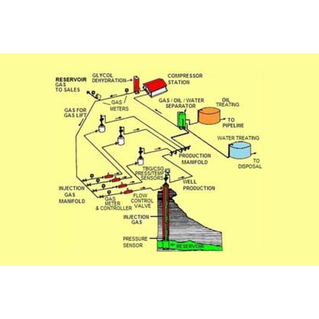
Overview of Gas Lift; Part 3: Operational Field Procedure for Identifying, Selecting, and Optimizing a Gas Lift Well
March 1, 2022
|
Tip of the Month
Part 3 of the Overview of Gas Lift series has procedures for identifying, selecting, and optimizing technical as well as field operations for a gas lift well.
View Article
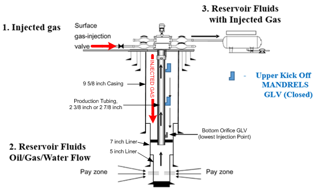
Overview of Gas Lift; Part 2: Operational Fundamentals for the Performance of a Gas Lift Well, Related to Choke Flow, Single Phase Gas, and Multiphase Flowing Gradients
February 3, 2022
|
Tip of the Month
In the Part 1 of this Series on Gas Lift History and Basic Well Parameters, an attempt was made
to bring into focus the primary “state of affairs” of Gas Lift operations in the USA.
Part 2 will discuss basic Gas Lift well casing and tubing components, and their operational
function, as well as Choke Flow relationships in Gas Lift wells.
In the Firs...
View Article
