Overview of Gas Lift; Part 3: Operational Field Procedure for Identifying, Selecting, and Optimizing a Gas Lift Well
March 1, 2022
|
Tip of the Month
Part 3 of the Overview of Gas Lift series has procedures for identifying, selecting, and optimizing technical as well as field operations for a gas lift well.
View Article
Overview of Gas Lift; Part 2: Operational Fundamentals for the Performance of a Gas Lift Well, Related to Choke Flow, Single Phase Gas, and Multiphase Flowing Gradients
February 3, 2022
|
Tip of the Month
In the Part 1 of this Series on Gas Lift History and Basic Well Parameters, an attempt was made
to bring into focus the primary “state of affairs” of Gas Lift operations in the USA.
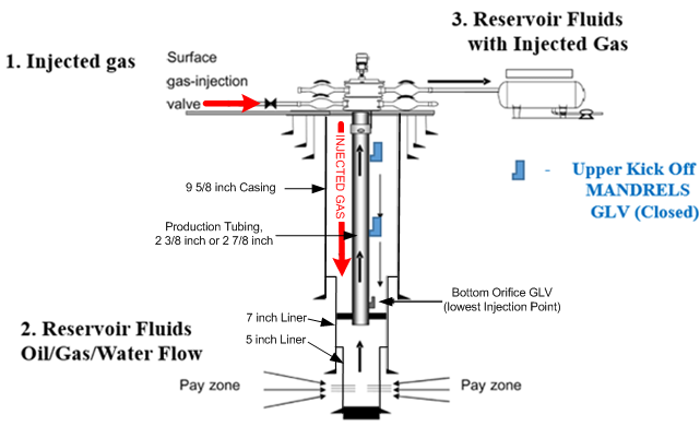
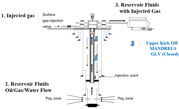
Part 2 will discuss basic Gas Lift well casing and tubing components, and their operational
function, as well as Choke Flow relationships in Gas Lift wells.
In the Firs...
View Article
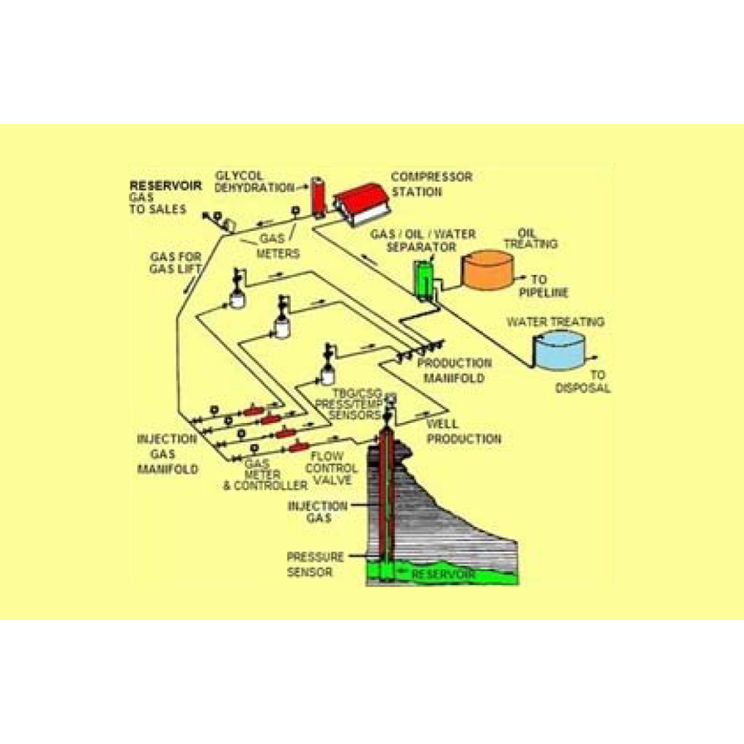
Overview of Gas Lift; Part 1: Gas Lift History, Fundamentals, Mandrels, Valve Types, and a Typical Field Installation
November 2, 2021
|
Tip of the Month
In this Part 1 presentation of the initial Gas – Lift series, and effort has been made to provide for initial orientation regarding the important Gas – Lift history, initial background, initial production efforts, Gas – Lift components, and design criteria. Oil and Gas production has been an integral part of the World’s energy based economy for ov...
View Article

Onshore Gas Gathering Systems – Concept Selection, Basic Design & Operation (Part 2)
August 30, 2021
|
Subsurface Topics
In some cases, a choke/line heater is required at the wellsite to deal with the large JT expansion cooling effect experienced by choked high-pressure wells, especially during start-up. This is a somewhat different application than prevention of hydrates in the GGS but there are some common aspects to the equipment utilized.
First, the hydrate temp...
View Article
The Diffusivity Equation
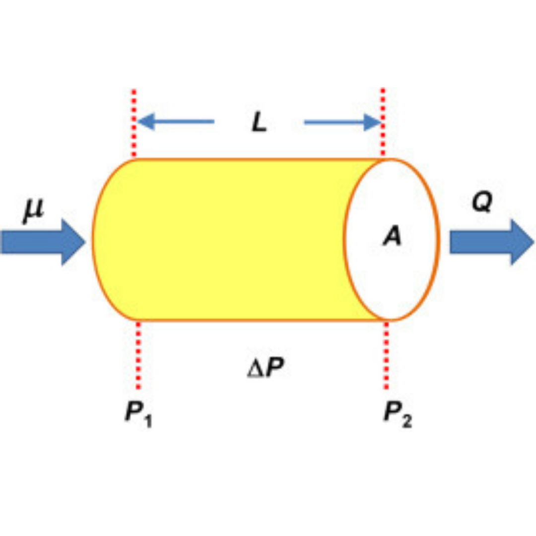
The theory of well testing begins with an understanding of fluid flow in porous media. In this article, the continuity equation, Darcy’s law, and equation of state for a slightly compressible liquid are used to develop the diffusivity equation, describing single-phase flow of a slightly compressible liquid.
View Article
Introduction to Well Test Interpretation
March 1, 2021
|
Tip of the Month
This article gives an overview of the types of well tests, well test applications, and the objectives of well test interpretation.
View Article