1.0 Introduction
LNG and gas processing plants often have some units that are identical; viz acid gas removal unit (AGRU), mol sieve dehydration unit (MSDU) and mercury removal unit (MRU). The degree of gas sweetening (AGRU) and the degree of water dew point depression (MSDU) is dependent on the requirement i.e., is the gas going to be transported in pipeline or is the gas is going to be further processed for LNG production. If mercury is present in the inlet gas, mercury removal would be mandatory due to both health and environmental reasons and aluminium metallurgical aspects.
In this TOTM, a closer look is taken on the possible causes of failure or of operational issues of the three processes mentioned above. Further, possible solutions are given in addressing these operational issues. But before going any further, let us consider what needs to be discussed prior to design, engineering and construction of a gas processing facility, or an LNG plant.
2.0 Some Typical Issues at the Design Stage of a Project [1]
At the design stage of a project, a critical review needs to be taken on the following aspects:
1. Has the upstream feed gas processing been adequately defined?
2. Have the contaminants/impurities levels been properly analyzed, discussed, and documented?
3. Is there sufficient understanding of the feed gas composition as well as processing steps?
4. What are the overall plant products slate and their specifications? In other words, is the economic case adequately addressed?
5. Have all environmental constraints been adequately identified and addressed in the design?
During this project stage, do not consider this as a stand-alone concept (think: plant life to be 25 years!). Some interfaces with upstream and downstream facilities need to be defined and it is important that unknown parameters attributed to start-up, and end-of-life, are identified/discussed, and their potential impacts assessed.
2.1 Some Typical Concerns and Risks at the Design Stage
Having worked on many gas projects, the author has identified the following crucial pitfalls at the design stage of a project.
Lack of understanding/knowledge of upstream processing units at summer/winter periods and normal/upset conditions. These could have significant impact on the overall design. Typical problems to address are [1]:
- Liquid slugs, formation water (think: what water cut is expected over 10, 20 years).
- If a multi-phase pipeline is used to handle gas, liquid hydrocarbons, and water, then handling of large quantities of liquids during pigging operations could impact operations of inlet receiving facilities and consequently handling of condensate handling facilities such as the 3-phase separator and condensate stripper (in some locations referred to as the condensate stabilizer).
- Undersized separators, particularly 3-phase separators at the inlet receiving facilities are a common problem.
- Presence of chemicals (glycol, methanol, corrosion inhibitors, hydrate inhibitors, compressor lube oils, etc) due to upstream operations such as field dehydration, etc.)
- Knowledge of sour feed gas heavy hydrocarbons distribution in the feed gas
- Feed gas composition needs to be analysed with complete breakdown to C12 to C20 fractions. It is not sufficient to have C5+ lumped together as one component for sizing the inlet equipment and liquid handling facilities for hydrocarbon rich gases. In specific instances where the feed gas compositional distribution is suspicious, an ASTM D-86 may be performed to evaluate ALL Alkane, and non-Alkane components in the gas.
- Presence of aromatics should be analyzed, as these components have a significant impact to the inlet fluids phase behavior and influence the design of amine regenerator and lean/rich amine heat exchanger.
- Inadequate or poor knowledge of sulphur compounds “traces” or distribution e.g., COS, mercaptan species, CS2, etc. If the gas is sour, these components should be analyzed to determine their presence and quantities as these can impact the selection of the AGRU.
- Gas composition ranges not identified, for example the H2S/CO2 max and min ratios; this dictates the Sulphur Recovery Unit line-up and can have a significant impact on the capital investment costs.
It is the responsibility of the Process Engineer to highlight the critical items that can impact the design and to propose reasonable design limits
2.3 Block Diagrams of Gas and LNG Plants
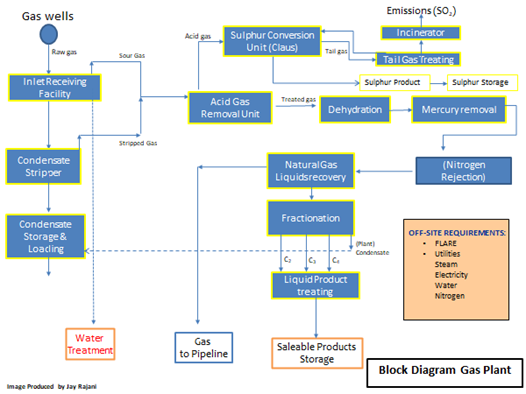
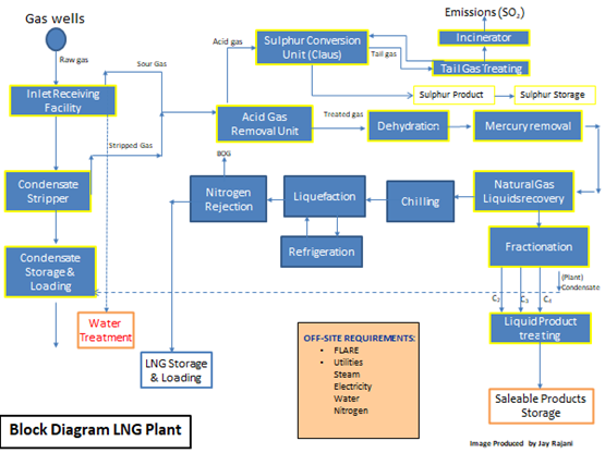
The following two figures show the block diagram of a typical gas plant and of a typical LNG plant.
Figure 1: Typical Process Block Diagram of a Cryogenic Gas Processing Facility
Figure 2: Typical Process Block Diagram of an LNG Plant
In the case of Figures 1 and 2, the commonality of the three basic processing units: AGRU, MSDU and MRU are illustrated. Failure in any one of these units would hamper the operations of any downstream process units and if the problem in any one of the units is not rectified, plant capacity would need to be decreased or a total plant shutdown initiated.
COMMON OPERATING PROBLEMS
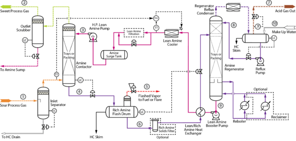
3.1 Troubleshooting AGRU [2,3]
Figure 3: Example Process Flow Diagram for an Acid Gas Removal Unit [5]
There are three most common classes of problems in AGRU:
- Causes of failure to sweeten: H2S, CO2 and total sulphur treated gas specifications are not being met. This could be due to inadequate regeneration of amine due to too high a circulation rate, insufficient reboiler heat input, reboiler problems, plugged or damaged regenerator trays or a leaking lean/rich amine exchanger.
- Foaming: Problem most often occurs at the contactor. Symptoms of foaming include a sharp rise in contactor differential pressure, loss of level in the contactor bottoms and severe carryover of amine into the outlet scrubber. It is almost certain that the treated gas will go sour whenever foaming occurs. Foaming is caused by a number of factors, but the most common in gas processing plants is the condensation of liquid hydrocarbons or ingress of other contaminants in the process gas stream to the amine contactor.
- Amine losses: The cost of amine can be a large operational expense, especially when it seems to disappear continually. Amine loss is an operational fact of life. When amine losses become excessive, however, it is a problem that requires troubleshooting. While normal amine loss is different for each of the different amines, losses in all systems occur due to the following four reasons [3]:
1. Mechanical loss: means that solution is physically lost from the system either due to carryover, foaming, and simple leaks at fittings and pump seals. Such losses are minimized with mist eliminators, foam prevention and the existence of a separate amine drain and recovery system
2. Solution Conditioning Loss: Practically a sub-category of mechanical loss, conditioning losses occur when a filter or reclaimer is not properly drained of solution during maintenance or change out activities. This type of loss is minimized by following proper procedures for solution displacement before draining and opening this type of equipment.
3. Chemical and Thermal Degradation: occurs when amines come into contact with oxygen and other components in the produced sour gas. Improper storage or oxygen in-leak are the main causes of oxygen contamination. Some amines are more susceptible than others to reactions with COS, CS2 and other sulphur compounds. All amines can degrade thermally if subjected to excessively hot heat transfer surfaces. Thermal degradation can be substantial at temperatures above 150°C (300°F).
4. Vaporization Loss: This type of loss depends upon amine type. For instance, MEA is 30 times more volatile than DEA, so we can expect vaporization losses in MEA systems to be substantially greater. Vaporization losses are usually minor and occur at both the contactor and the regenerator of the AGRU.
3.1.1 Foaming in AGRU [3]
There are innumerous papers and technical publications on foaming. Here a brief overview of potential foaming causes are given:
- Dirty amine containing iron sulphide or diatomaceous earth. Both are foam promoters, as are well treatment chemicals that find their way into the system due to insufficient upstream separation.
- If corrosion inhibitors are in use, they may be the culprits as these inhibitors are surface active species. One of the most common promoters of foaming can be (surprisingly) anti-foam products that are injected to stop foaming.
- Foaming is predominantly prevented by all those things already discussed in other sections, like preventing hydrocarbon condensation, using a filter/separator on the inlet and keeping the solution clean.
- Once it starts, however, you must focus on short-term solutions instead of trying to correct long-term design issues. Immediate short-term solution is to try injecting some anti-foam chemical (unless a bunch has already been put in) and/or reducing the inlet gas rate. If these actions help, you can then track down the real cause and hopefully correct it. If anti-foam does not help, do not inject any more. Too much anti-foam can make things worse.
- It is important to note that the choice of an antifoam agent needs to be considered carefully. In general, silicone-based antifoam agent should be used in an amine-based solvent. The use of alcohol-based solvent is often preferred in hybrid or mixed solvent (mixture of physical solvent and amine solvent). Check with the amine vendor on their recommendation.
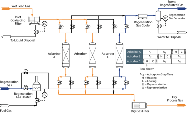
3.2 Troubleshooting Mol Sieve Dehydration Units (MSDU) [3, 4]
Figure 4: Example Process Flow Diagram for a Molecular Sieve Dehydration Unit [5]
Most operating problems that can occur in MSDU are:
- The adsorber produces specification product (i.e., water content at the outlet of the absorber) part of the time, but not for the entire cycle.
- The adsorber does not produce specification product at any time in the cycle.
- Pressure drop in the adsorber becomes so high that gas flow must be reduced due to lack of adequate pressure, or for fear of damage to internal bed support structure.
3.2.1 Low Water Adsorption Capacity on the Mol Sieve Bed
1. When the adsorption capacity is low, the plant produces specification outlet product during the first part of a cycle, and the product is off-spec during the latter part. When an adsorber indicates inadequate capacity, it is easy to decide that the adsorbent needs to be replaced. This could be the case, but a few checks should be made before investing in a new adsorbent bed.
A short-term solution could be to reduce the adsorption time but that reduction is limited to the time required to properly regenerate an exhausted adsorber bed.
2. Ensure the inlet gas conditions (P & T) have not changed, thereby increasing water load entering the adsorber compared to design. A relatively small increase in feed temperature can increase the water load significantly, typically, 1⁰C (1.8⁰F) temperature increase of the gas would increase the gas water content by roughly 6%.
3. Other seemingly minor changes in operating conditions can have equally dramatic influence on the operation of an adsorber. A change in the wells, or formation from which the feed comes, can be important. Remember how various other components can compete for space on the adsorbent pore surface. Check to make sure the feed does not contain oxygenates (methanol), glycol or other chemicals that are injected routinely in operations.
4. Make certain that the meter used to measure the dew point or other contaminants is accurate. The test cells used in many modern instruments will occasionally pick up contamination which alters their level of response. It is good practice to keep a spare cell, or probe, and check the system periodically. Alternatively, one can consider installing two analyzers on the outlet.
5. Make certain that liquid hydrocarbons are not entering in the inlet gas to the adsorber. If this is the situation, the liquid hydrocarbons will coat the adsorbent and make the bed operate as if it were in a liquid system. In that case, the transfer of water from gas to adsorbent is very slow, thus the mass transfer zone is much longer than normal. This means there is less adsorbent to reach dynamic equilibrium and consequently the mass transfer zone is being extended. The result is a drastic decrease in capacity of the adsorber, and premature break-through.
6. Monitor the pressure drop across the bed. If there is a sudden increase in bed pressure drop, it can mean that some contaminant has entered the bed, or that the adsorbent beads or pellets have broken up. In either case the result may be poor flow distribution through the bed, and a resultant fast break-through. On the other hand, if the pressure drop suddenly falls quite a bit, it could mean that the adsorbent bed support has developed a leak and part of the adsorbent has been lost. This can be a significant problem in plants that do not have filters on the outlet of the adsorption plant. Typically, start-of-run ΔP would be 0.6 bar [8.7 psig] and end-of-run would be 1.2 bar [17.4 psig].
7. Make certain switching gas valves are not leaking. Feeling the outlet end of a closed valve during the heating phase is an easy way of detecting a leak. If the piping is hot, the valve is leaking.
3.2.2 Mol Sieve Degradation [4]
Deactivation of a portion of the molecular sieve in natural gas dehydration units is inevitable. Typical degradation resulting in sieve deactivation include:
- Thermal degradation (is unavoidable)
- Caking (is avoidable)
- Coking (could be due to heavies such as heavy hydrocarbons, or gas treating solvents being adsorbed at the start-of run, thus difficult to avoid if present in the feed gas)
Deactivation can be more severe in the case of cake or coke formation. In time, the capacity at the top of the bed will be lower than at the bottom of the bed and this is often referred to as “capacity gradient”.
Let us look at more closely to these degradation phenomena.
3.2.2.1 Thermal Deactivation
With each thermal swing, the water adsorption capacity of the molecular sieve will decrease (thermal degradation). Thermal degradation will always occur.
Fines and dust formed during the regeneration cycle can also accumulate on the mercury removal bed downstream and result in an increased ΔP of that bed. This can result in the possibility for retrograde condensation in the downstream bed.
How do you improve this? Optimise regeneration frequency (minimize number of regeneration cycles by applying variable cycling). At the start of the unit, there is adequate water adsorption capacity as the unit would be designed for end-of-life (i.e., lower) adsorption capacity. This means that longer adsorption cycle time could be used, thus minimising the number of regeneration cycles. This normally would extend the life of the mol sieve unit before a mol sieve change out is executed. A performance test run (PTR) is often used to determine the degradation profile of the adsorbent bed.
3.2.2.2 Caking - Hydrothermal Deactivation
Caking is a term used to describe the loss of zeolitic and/or binder structure.
This can be caused by:
1. the presence of liquid water on the bed during regeneration (can be avoided by using a proper regeneration temperature profile).
2. liquid carry-over from an upstream unit. The cause of this is most often feed gas knock out drum upstream of the mol sieve bed being undersized or the mist extractor in the KO drum is not effective in catching fine liquid droplets that are being carried into the mol sieve bed. Best practice is to use an adequately sized inlet coalescing filter separator rather than a conventional KO drum.
How do you improve this? Optimise the regeneration cycle i.e., slowly ramping up the temperature of the bed under regeneration to avoid formation of water on the top head / upper walls of the vessel during the heating cycle and check the KO drum sizing upstream of the MSDU.
3.2.2.3 Coke - Hydrocarbon Entrainment
Coking is a term used to describe blocking of micro and macro pores by (carbon) deposits. This is caused by the presence of ‘heavy’ components in the feed (e.g., amines, BTEX, C20+). Once adsorbed during the adsorption cycle (this shall occur when the mol sieve is still fresh at start-of-run), these heavy components crack during the regeneration cycle causing coke on the mol sieve material. This often hinders the mass transfer phenomena and reduces the water uptake capacity on the sieve material.
How do you improve this? At the design stage, always think of installing a layer of guard material (silica-gel or alumina) on top of the mol sieve bed. Such a guard layer protects the mol sieve bed by “catching” impurity droplets upstream of the mol sieve bed. This must be done during the design stage so that there is adequate vessel capacity to hold the required mass of the sieve and the guard material layer.
4.0 Troubleshooting Mercury Removal Unit (MRU)
Most common adsorbents used for the removal of metallic mercury are:
- Sulphur impregnated carbon:
- Metal Sulphided Adsorbents consisting of CuS and ZnS or PbS:
If early breakthrough of mercury is detected, the most likely causes to investigate are:
- Check if the mercury analyzer has calibration issue.
- Check if the mercury content in the feed gas to the LNG / Gas Plant has changed due to the change in the upstream operating wells.
- Check the phase envelop of the feed gas entering the MRU. Is there possible retrograde condensation or any liquid fall out on the adsorbent bed? If yes, it is possible that the sulphur that is impregnated on the activated carbon has leached out causing the adsorbent to be inactive in mercury capture. If a metal sulphided adsorbent is used, then the liquid fall out is causing slower mass transfer rates and both saturation and mass transfer zones are much longer than the design case, causing an early breakthrough of mercury at the outlet of the MRU.
There is new adsorbent on the market that has been developed by Queen's University's Ionic Liquids Laboratory (QUILL) and Petroliam Nasional Berhad (PETRONAS). The process, marketed as HycaPureHg™, captures all mercury species present in natural gas and the researchers claim that it has up to 3 times higher capacity than competing state-of-the-art commercial alternatives.
The jury is still out as we await publication of the results on the trials carried out on Malaysian LNG plants.
5.0 Concluding Remarks
In this TOTM, we discussed some common operational issues of the three critical process units in LNG and Cryogenic Gas Processing Facilities.
Troubleshooting these units requires a good understanding of the feed gas components and the possible contaminants that would affect optimal operation of these units.
If the reader is interested further on these subjects, we suggest attending our G4 (Gas Conditioning and Processing); G4 with LNG Emphasis, G6 Gas Treating and Sulphur Recovery, or our new 3-day short courses on Acid Gas Removal Fundamentals, and Molecular Sieve Dehydration Fundamentals courses provided by PetroSkills/JM Campbell.
References:
1. The Basics of Gas Treatment for Liquefaction Plant by J. Castel, Paper presented at the GPAE held in Hamburg, Germany, 23rd April 2015
2. Gas Conditioning and Processing, Volume 4: Gas Treating and Sulphur Processes by R.N. Maddox and D. John Morgan, John M. Campbell Publications
3. Introduction to Oil and Gas Productions Systems, Version: BP-IEP_01.03.2004
4. Finding the Fountain of Youth for a Mol Sieve Dehydration Unit by A.F. Carlsson
J.B. Rajani, and A.J. Kodde, Paper presented at the 83rd GPA convention held in
New Orleans, USA, March 2004
5. Campbell, J.M., “Gas Conditioning and Processing, Volume 1: The Fundamentals,” 9th Edition, 3rd Printing, Editors Hubbard, R. and Snow–McGregor, K., Campbell Petroleum Series, Norman, Oklahoma, PetroSkills 2018


