Well documented oilfield industry statistical data illustrate that different types of corrosion are a prime factor related to approximately 1 in 3 occurrences of equipment failures. By far, corrosion is the most significant and troublesome mechanism in the oilfield. It results in production shut-in and loss of revenue in addition to repair and remediation costs. As wells are completed in deeper, higher pressure, and higher temperature reservoirs (referred to as HP/HT conditions), materials selection based upon performance in extreme conditions has become critical to avoiding catastrophic failure under these conditions. A major challenge when working in HP/HT conditions is determining accurate materials performance data. A broad area of research to evaluate materials' resistance to corrosion and cracking, as well as resistance to fatigue forces at elevated pressures and temperatures continues as HP/HT conditions are more frequently encountered at deeper formation depths. One example is the regular and necessary use of duplex stainless steels, which offer excellent corrosion resistance and provide mechanical strength, albeit at a significant cost premium. Corrosion in the oilfield often appears as leaks and overall failures in tanks, casing, tubing, pipelines, and other subsurface and surface equipment. Base metal disappears as corrosion cell mechanisms result in refined metals always striving to reverting back to their native state. Metal ores are mostly oxides and sulfides, which are more stable than pure metals. Energy is required to reduce the ore and produce metal, as occurs in a blast furnace. Most metals are like fuels; they tend to combine with oxygen, sulfur, and other elements in chemical reactions. These combining reactions of metals produce heat or some other form of energy and change the metals back to more stable compounds. Metals such as zinc and magnesium are more reactive and release more energy when they corrode, than do metals such as silver and gold. Zinc is extensively used as a sacrificial anode to protect offshore structures from corroding. Silver and gold do not corrode readily but are too expensive to be used as a means of reducing corrosion.
The objectives of this article are to:
- Explain why and how metals corrode
- Describe the various types of corrosion
- Illustrate methods that are used to detect and measure corrosion
The Corrosion Cell - Why and How Metals Corrode
Four elements are necessary for corrosion to occur:
- Anode
- Cathode
- Electrolyte (water)
- Metallic path for electron flow
When all four elements are present, a corrosion cell exists. Figure 1 illustrates a corrosion cell and shows these four elements. The anode and cathode may be located at two different locations on the same metal surface, or they may be two dissimilar and separate metal samples. The first case is shown in Figure 1, where a grain boundary corrodes because it is anodic with respect to an adjacent grain body. In the second case, the threads of a steel nipple are made up in a bronze valve body, the bronze becomes the cathode, and the steel will be anodic and corrode. Examples of electrolytes are oil field brines, moisture in soil, and seawater.
The metallic path is usually through the object that is undergoing corrosion. When the anode and cathode are separated by some distance, it is frequently possible to stop corrosion by interrupting the metallic path. Thus, in the previous example of the steel nipple and bronze valve, it may be possible to electrically isolate the two metals with a plastic bushing, or to isolate the threads with Teflon® tape. Corrosion caused by this dissimilar metal or galvanic couple will cease unless there is a continuous path for electron flow from the nipple to the valve. Electric current flow, illustrated in Figure 1, is in the opposite direction to electron flow.
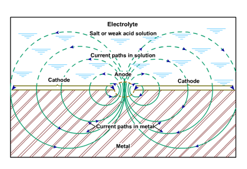
Figure 1 - Flow of current from a corroding pit.
In the corrosion of iron in a weak acid solution, such as many oilfield brines, iron goes into solution as ferrous ions at the corroding or anodic surface, leaving two negative electrons in the metallic iron:
Feo → Fe++ + 2 (electrons) -
(Iron) (Ferrous ion) (Remain in Iron)
Equation 1
The negative electrons in the metal move toward noncorroding or cathodic areas, and hydrogen ions in the solution react with these electrons at the cathode, forming hydrogen gas that bubbles off:
2H+ + 2 (electrons) - → H2o
(Hydrogen ion) (Hydrogen gas)
Equation 2
A metal surface is often covered with corrosion cells, with some areas being anodic and others being cathodic. The individual anode and cathode areas are called half-cells, and each has an electrical potential that is opposite in polarity to the other. Impurities or imperfections in the metal contribute to the formation of anodic and cathodic areas on a metal surface.
As previously noted, corrosion is associated with flow of electric current. In a metallic circuit, electric current can be predicted by Ohm's Law. The amount of current, I, is directly proportional to the applied voltage, E, and inversely proportional to the resistance, R:
Equation 3
In the electrochemical corrosion circuit, electric current flows from the anodic areas into the electrolyte and then flows from the electrolyte into the metal at cathodic areas. Corrosion inhibitors and coatings impede or reduce current flow, usually by increasing resistance in the electrochemical corrosion circuit.
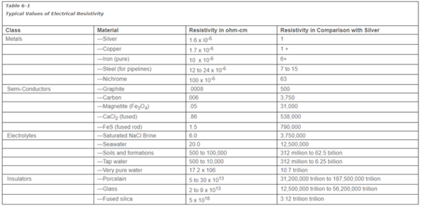
Because corrosion involves flow of electric current through many materials, it is necessary to consider the electrical resistivity of each.
Effective resistance (R) to current flow through a material or electrolyte is inversely proportional to the cross-sectional area (A) of the object, and directly proportional to the length (L) of the current path. This is represented by the equation
Equation 4
or, using the symbol, ρ, for a proportionality constant,
Equation 5
Resistivity is the name frequently used to refer to the proportionality constant ρ. This proportionality constant (ρ) is unique for each material or electrolyte. If the units of L and A are cm and cm2 respectively, and R is expressed in ohms, the above equation shows the units of ρ will be ohm-cm.
Materials in Table 1 are arranged in order of increasing resistivity. Note the extreme range between metals and the best insulators.
Seawater or brine is usually considered a good conductor compared to distilled water. Some corrosion products, such as magnetite or ferrous sulfide, are better conductors than brine or seawater.
Many questions regarding the flow of cathodic protection currents can be explained through consideration of Table 1. For example, an insulating joint in an uncoated well flowline containing produced water will almost completely stop the flow of current to the well, although the pipe is filled with material of relatively low resistivity when compared to good insulators.
Table 1 Typical Values of Electrical Resistivity
At the cathodic spot where the electrical current enters the metal (Figure 1), bubbles of hydrogen gas form on the metal surface, but no metal loss occurs at that spot. The cathodic half-cell reaction that generates hydrogen is depicted in Eq. 1. Hydrogen gas clinging to the cathode location increases resistance to current flow; so the current flow and the corrosion rate are simultaneously reduced. As the hydrogen generating reaction proceeds, the electrical potential of the cathode half-cell is reduced, and thus current flow in the whole cell is reduced. A change in half-cell potential is called polarization.
Pounds of iron loss from an anode are proportional to the current flow in the whole cell. One ampere of current flowing for a one-year period will remove 20 lb of iron. For perspective, a 1/8-in. diameter hole in tubing represents about 1/100 ounce of metal loss.
Types of Corrosion
The primary forms of corrosion in production operations are metal pitting, cracking, grooving, and wall thinning. These effects are easily seen but require detailed study to find the cause. Thorough knowledge of the environment, location in the system, operating history, and metallurgy of the corroded item are necessary in diagnosing the causes and prescribing a cure for the corrosion problem.
Factors in the environment that must be determined by field or laboratory measurement include electrolyte properties (resistivity, chlorides, pH, etc.), temperature, pressure, CO2, H2S, content, and bacteria presence and type.
In the case of pipeline or well casing corrosion, location information should include proximity to stray current sources. Insulating flanges installed at critical locations in flowlines often eliminates or greatly reduces stray currents from electrical motors and thus corrosion problems in well tubing and casing are reduced.
In addressing corrosion problems, operating history should be gathered, including such information as previous inhibitor treatments, acid treatments, producing rates, water-oil ratio, and handling damage.
Failure analysis usually reveals that presence of CO2, H2S, or O2 is the principal cause of corrosion. Pitting and cracking usually starts at surface scratches, gouges, or dents. Differences in metal micro-structure and inclusions often cause one area of metal to become anodic to another. When CO2, H2S, and O2 are present, that anodic area can corrode at a high rate.
In the absence of CO2, H2S, or O2, water is usually not corrosive at normal oilfield temperatures. Unfortunately, one or more of these gases is almost always present in varying quantities in production operations.
Various treatments of the metal, such as scratches, tong marks, hammer marks, greases, and paint, as well as the original heat treatment or imperfections in the basic metal at grain boundaries control the location of the cathodic and anodic areas. Physical damage appears in the form of pits, holes, cracks, general metal loss, and loss of strength or ductility.
Detection and Measurement of Corrosion
Finding Corrosive Environments
Corrosion can be prevented or reduced if a corrosive environment is recognized. Early detection of active corrosion will allow initiation of control measures and usually will prevent serious damage.
How can active corrosion be identified before a catastrophic failure or irreparable damage occurs? Searching for factors that increase corrosion rates is the initial step. If any related factors are present, measuring the corrosion rate using corrosion coupons or probes will provide a definition of base line corrosion rates. If metal loss is determined to be not significant, it may be cheaper to allow the corrosion to continue than to combat it.
Identify Potential Sources of Corrosion
The first step in controlling corrosion is the identification of corrosion-causing factors; visual inspections may or may not be adequate. Chemical, bacteriological, or electrochemical tests are usually made to verify conclusions. Some of the factors that contribute to corrosion follow:
- Water must be present before corrosion can start. The water may be oilfield brine, fresh water, water spray, vapor, or condensation.
- In oil or gas wells, acid gases, hydrogen sulfide, and carbon dioxide form acids when dissolved in water. Hydrogen sulfide may be generated by sulfate-reducing bacteria in waters containing dissolved sulfates.
- Air (oxygen) enters oilfield systems by the "breathing" of vessels through the casing-tubing annulus, from packing leaks at pumps and valves, from faulty gas blankets, or, from malfunctioning vapor recovery systems and other sources. Trace amounts of air can cause severe pitting. Oxygen probes to measure oxygen in flowlines are technically challenging and costly to use but they may be valuable in pinpointing oxygen entry points.
- Dissimilar metals in physical contact will cause galvanic corrosion. Some common occurrences are brass valves in steel lines, brass polished rod liners, and bronze pump impellers in steel cases.
- High fluid velocities or turbulence can remove protective films. This can be a problem in high-capacity gas wells, high-speed centrifugal pumps, throttling valves, chokes, and heat exchangers.
- Concentration cell corrosion occurs in many situations:
- Pipelines: External corrosion of lines crossing cultivated fields, brine-polluted areas, caliche beds, and roads is common. Internal corrosion of lines handling fluids with considerable suspended corrosion products, loose scale, or other solids is also common.
- Well Casings: External corrosion will often result from faulty electrical insulation between wellhead and flowline or gas gathering lines. Oil wells with known casing leaks should be periodically checked for external corrosion. Internal corrosion is frequently caused by the "breathing" of air if the casing-tubing annulus is open to the atmosphere.
- Vessels: External corrosion of tanks occurs when tanks are set on soil foundations, with drain lines buried beneath tanks, and in crevices where moisture can collect between tank and supports. Internal corrosion will occur by "breathing" air into vessels, from faulty gas blankets, and from solids accumulation on tank bottoms.
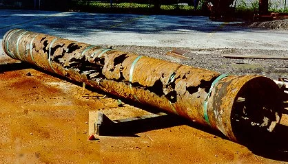
Figure 2 - Example of corroded casing.
It is usually impossible or too expensive to stop all corrosion. Corrosion may sometimes be allowed to proceed at an acceptable rate if the projected economic loss from corrosion is less than the cost of corrosion control and if safety concerns are rigorously identified and addressed. For example, in many areas, lease production equipment may not be internally or externally coated for corrosion control if damage occurs at a slow rate. However, various vessels should be internally coated where corrosion it is expected that corrosion might cause serious damage.
Corrosion inhibitors treating practices and programs are implemented widely, but it is imperative to regularly and thoroughly assess their effectiveness. Chemical compatibility of inhibitors used in field flowlines and wells must be assured and coordinated with those inhibitor chemicals used within treating plants facilities.
The degree of corrosion control adopted is also influenced by safety codes and standards, governmental regulation and environmental considerations. There are several ways to minimize corrosion in oilfield operations which include materials selection, engineering design, inhibitors, coatings, removal of corrosive gases, cathodic protection and use of non-metallic materials.
If you are interested in learning more about oilfield corrosion, we recommend enrolling in an upcoming session of Production Operations 1 or Corrosion Management in Production/Processing Operations. Both courses are also available in online formats – view the schedule here.
References
1. Fontana, M. G., and Greene, N. D.: Corrosion Engineering, 2nd Ed., McGraw-Hill, New York.
2. "Practical Tips in Trouble Shooting Pumping Wells," Pet. Eng. (Feb. 1959) pp. 60-66.
3. Keene, John D. (ed.): Steel Structures Painting Manual, Volume 2—Systems and Specifications, 2nd Ed., Steel Structures Painting Council, Pittsburgh, PA (1964).
4. Wright, C. C: "Applying Instantaneous Corrosion Rate Measurement of Waterflood Corrosion Control," JPT (March 1965) p. 269.
5. Peabody, A. W.: "Control of Pipeline Corrosion," NACE (Dec. 1967).
6. Uhlig, H. H.: Corrosion and Corrosion Control, 2nd Ed., John Wiley and Sons, New York (1971).
7. Frank, W. J.: "Efficient Removal of Oxygen in a Water-flood by Vacuum De-aeration," SPE 4054 (Oct. 1972).
8. Choate, Leonard C: "New Coating Developments, Problems, and Trends in the Pipeline Industry," NACE Paper No. 34, presented at the NACE meeting, Chicago, IL (1974).
9. Schremp, F. W., and Robertson, G. R.: "Effect of Supercritical Carbon Dioxide (CO2) on Construction Materials," SPE (June, 1975) p. 227.
10. Newton, L. E., Jr., and McClay, R. A.: "Corrosional and Operational Problems, CO2 Project, Sacroc Unit," SPE 6391, Permian Basin Oil and Gas Recovery Conference of SPE of AIME, Midland, TX (March 1977).
11. Heinrichs, H. J., Ingram, W. O., and Schellenberger, B. G.: "Cathodic Protection Requirements for Well Casing," Pet. Soc. of CIM (June 1977).
12. Wheeler, D. W., and Weinbrandt, R. W.: "Secondary and Tertiary Recovery with Sea Water and Produced Water in the Huntington Beach Field," SPE 7464 (Oct. 1978).
13. "National Association of Pipe Coating Applicators Specifications and Plant Coating Guide," National Association of Pipe Coating Applicators, Shreveport, LA (1979).
14. Sum X Corporation: "Corrosion Due to Use of Carbon Dioxide for Enhanced Oil Recovery," Final report of work performed for the DOE under contract DE-AC21-78MC08442 (Sept. 1979).
15. Adams, Gene H., and Rowe, Hunter G.: "Slaughter Estate Unit CO2, Pilot-surface and Downhole Equipment Construction and Operation in the Presence of Hydrogen Sulfide Gas," SPE 8830, Joint SPE/DOE Symposium on Enhanced Oil Recovery, Tulsa, OK (April 1980).
16. Saul, Harry E., and Detterick, Jerry A.: "Utilization of Fiberglass Sucker Rods," JPT (Aug. 1980).
17. Houghton, Christopher J., and Westermark, Robert V.: "North Sea Downhole Corrosion Identifying the Problem; Implementing the Solutions," JPT (Jan. 1983) p. 239.
18. Huntoon, George H.: "Completion Practices in Deep Sour Tuscaloosa Wells," JPT (Jan. 1984) p. 79.
19. Schremp, F. W.: "Corrosion Prevention for Offshore Platforms," JPT (April 1984) p. 605.
20. Jonathan J. Wylde, Geoffrey C. Allen, University of Bristol, Interface Analysis Centre; Ian R. Collins, BP Exploration, Upstream Technology Group, “A Surface Sensitive Study of the Influence of Corrosion Inhibitor on Chemical Scale Inhibition,” SPE 74677-MS (Jan. 2002).
21. Richard L. Martin, BJ Unichem Chemical Services, “Unusual Oilfield Corrosion Inhibitors,” SPE 80219-MS (Feb. 2003)
22. H. A. Craddock, SPE, S. Caird, and H. Wilkinson, Roemex Limited; and M. Guzmann, BASF De, “A New Class of "Green" Corrosion Inhibitors: Development and Application,” SPE 104241-PA (Dec. 2007).
23. Dr. D. C. Buxton and Dr. D. G. John, CAPCIS Ltd., “Cathodic Protection System Life Assessment,” SPE International Oilfield Corrosion Conference, 27 May 2008, Aberdeen, UK, SPE 114134-MS.
J. Marsh and T. Zvandasara, Wood Group Integrity Management; A. Macgill and J. Kenny, J. P. Kenny Caledonia: “Materials Selection For HP/HT Developments,” SPE International Conference on Oilfield Corrosion, 24-25 May 2010, Aberdeen, UK, SPE 130716-MS.
