Raw natural gas that is produced from the reservoir always requires some type of conditioning and processing before we can transport that gas to the customers. Why is gas conditioning and processing necessary? Because our sales gas, and liquid hydrocarbon products that we produce must meet the sales / product specifications. These specifications are set contractually by: 1) the buyer, 2) the transporter, or 3) by subsequent processing requirements. These product specifications are largely driven around safety in the transportation, end use of the various commodity streams, or the process operating conditions of downstream operations. Figure 1 provides a simplified schematic of the Natural Gas Value Chain.

Figure 1. Gas Gathering and Processing in the Total Production System[1]
As one can see from Fig. 1, natural gas can be produced from many different types of reservoirs. Unfortunately, there is no “typical” natural gas composition, the composition of the gas that comes out of the ground is set by the reservoir compositions and types, which can vary widely. The first constraint in figuring out the unit operations that are required in the gas conditioning and processing module, is understanding the inlet gas composition. So, let’s take a quick review of the various reservoirs that are shown in Figure 1 and discuss the possible hydrocarbon compositions and some common terminology used in the industry.
Let’s start with the oil well, shown in the figure on the far left. Notice, when the produced oil flows to production separator 1 in the figure, the oil flashes off some amount of solution gas. The solution gas flowing from the production separator was in the oil phase at reservoir conditions. As a result, this gas is very rich in heavy hydrocarbons. One of the key parameters in determining the gas conditioning and processing requirements is how much heavy hydrocarbons are present in the gas. Often times, the solution gas is processed to recover the additional heavy hydrocarbons from this gas stream as condensate and natural gas liquids (NGLs). The crude oil from the production separators would be processed and transferred to the end buyers. Notice the solution gas is shown going through some field treating (typically TEG Dehydration) and Compression (optional depending upon reservoir pressures and gathering system layout) before it flows to the Gas Processing Module. Notice, from the gas processing module, there are two streams that are shown going back to the oil well, CO2 for EOR (Enhanced Oil Recovery) and Gas Lift and / or Injection. CO2 EOR, is outside of the scope of the TOTM.
Commonly, solution gas that is produced with crude oil is used for gas lift. Gas is injected into the several gas-lift valves positioned along the well depth which are used during start-up. Once the well is started-up all of the valves are closed, except for the valve at the bottom remains open. The flow of gas is used to decrease the density of the crude in the well to allow for higher crude production rates at the same differential pressure. Or the gas may be reinjected into the reservoir to prolong and maintain the gas cap pressure which provides the drive mechanism for crude oil to flow up the well bores. This will also increase recoveries and the life of the field.
Let’s move to the next gas well with Production Separator 2, which is shown producing natural gas from the gas cap of the oil reservoir (often referred to as associated gas), AND gas from a conventional non-associated gas reservoir. Notice, in both cases, the gas that is being produced is in the vapor phase at reservoir conditions. This implies that these gases have a lighter composition than that of the solution gas. In terms of the conventional non-associated gas reservoir, non-associated gas only refers to the fact that the gas is “not associated” with any oil at reservoir conditions. Conventional refers to traditional reservoirs (hydrocarbons and water) that has sufficient porosity to hold economic quantities of hydrocarbons, and has permeability to allow the production of these fluids. The reservoir is sealed by non-permeable rock, which essentially traps the fluids in the reservoir. For conventional non-associated gas reservoirs, the composition can range from lean to rich really depending upon the reservoir type, for example is it a wet-gas (rich, or wet with heavy hydrocarbons) or dry-gas (lean – very little if any heavy hydrocarbons). Sometimes wet / dry gas can be confused with water content. It should be noted that all production from the reservoirs will be saturated with water, which is the most common contaminant in natural gas that must be removed.
Notice, from Production Separator 2, that field condensate is being separated from the produced natural gas. When rich gas is produced from a reservoir, the heavy hydrocarbons (C5+) will be in the liquid phase at production separators temperatures and pressures. This field condensate is often blended into the crude oil provided the crude oil vapor pressure specification is not exceeded (as shown in Figure 1). This is done because crude oil had a higher commodity value than field condensate, thus maximizing revenue from the field production.
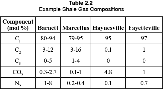
Let’s move now to Production Separator 3. This production separator is producing from an “unconventional gas reservoir”. A few examples would be a shale gas reservoir, a tight gas reservoir, or even coal bed methane (CBM). Shale gas is often referred to as “resource plays” because the gas is trapped in the rock (like air in pockets trapped in bread). The reservoir has very low permeability, thus fracking is required to produce these wells. Shale gas can range from very lean and dry to very rich in heavy hydrocarbons, with the composition changing within a single shale play depending upon the depth and zone of the production. Table 1 provides some example compositions from North American Shale Plays that highlights the variability in composition.
Table 1. Example Shale Gas Play Compositions [2]
CBM is similar to shale gas, except the gas is absorbed in the matrix of coal. The gas composition is primarily methane, with possibly some CO2 / N2 and water. As a result of CBM being primarily methane, this produced gas requires much less processing than the others as there are no potential hydrocarbon liquids to recover to sell.
So, as was discussed here, the inlet gas composition to a gas processing facility can vary significantly. The processing steps required for a given inlet composition to meet the sales gas and possibly liquid product specifications is dependent upon that inlet gas composition.
Essentially, STEP 1 – Know your fluids
Now that the inlet composition is understood, the next part of determining what processing will be required is determining what products the facility is going to produce. This decision sets the ultimate design of the plant. There are a number of factors that play here:
1. Probable forecast of reservoir performance / or size of shale play and drilling / production plans
2. Local commodity markets and access to those markets
3. Local infrastructure available
4. Capital and Operating Costs of the various processing options
If we look back at Figure 1, let’s focus on the products that a gas processing facility makes and their uses.
Sales Gas (often referred to as Residue Gas) – natural gas that we use in our homes
LNG – Liquified Natural Gas – means of transporting large volumes of gas to distant markets
GTL – Gas to Liquids – process that converts natural gas into lube oils, diesel, etc.
NGLs – Natural Gas Liquids – these can be sold as pure commodity products
Ethane – Petrochemical feedstock for manufacture of ethylene
Propane* – Petrochemical feedstock for manufacture of propylene / residential, commercial and transportation fuel
Iso-Butane – Refinery feedstock to alkylation unit / fuel use as LPG
Normal Butane – Gasoline (petrol) blending, petrochemical feedstock for manufacturing light olefins, fuel use as LPG, and can be isomerized to i-C4
Natural Gasoline** – Refinery feedstock to reformer or isomerization unit, petrochemical feedstock for manufacture of light olefins
* Often sold as liquified petroleum gas (LPG) which can be C3, C3-C4 mixture or predominantly C4
** Natural gasoline is a North American term, also referred to as raw gasoline, light naphtha or condensate in other regions
It should be noted, that heavier hydrocarbons have a higher market value as compared to natural gas. When a facility is designed to do NGL extraction, the processor is taking advantage of this price differential between the NGL products (ethane + heavier hydrocarbons) and its value as a natural gas constituent. The value of NGL product as a natural gas constituent is termed the “shrinkage value”. This represents the value foregone by extraction of the NGL from the gas. So, for example, if one were to take all of the propane out of a natural gas stream that would have been sold in the sales gas stream, the sales gas stream “shrinks” because those propane molecules are removed and being sold as a liquid product stream, that typically, has higher value than the sales gas stream. Shrinkage is the highest operating cost in terms of an NGL extraction facility and must be taken into account. I will write more about this in an forthcoming tip of the month.
STEP 2 – Define the products you want to make
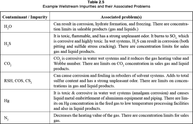
Now that the products of a facility are defined, the appropriate gas conditioning and processing unit operations can be selected. Let’s take a quick look at what contaminants may be found in produced natural gas and their associated problems. Note, these contaminants will need to be removed to meet the appropriate sales gas and liquid product specifications.
Typical well-stream impurities along with their associated problems are listed in Table 2.
Table 2. Example Impurities and their Associated Problems [2]
STEP 3 – Identify the contaminants that need to be removed, and to what level
The determination of what contaminants need to be removed and at what level depends upon multiple factors. Each product commodity has its own product specifications, which as mentioned previously is either set by 1) the buyer, 2) the transporter, or 3) by subsequent processing requirements or regulations. For example, if we are in a situation where there is an ethane market is available, the gas composition fits, etc.., then we will need to go into a deep NGL extraction unit which requires cryogenic temperatures. This would be an example of subsequent processing requirements where the process operating temperature requires further contaminant removal (bone dry water content), than say a pipeline sales gas specification. For cryogenic processing, there are also tighter specifications on CO2 concentrations as well, as CO2 can freeze in the cold box (think dry ice).
With that said, let’s take a quick look at some typical pipeline sales gas specifications from around the world, as shown in Table 3.
Table 3. Example Sales-Gas / Transportation Specifications [2]
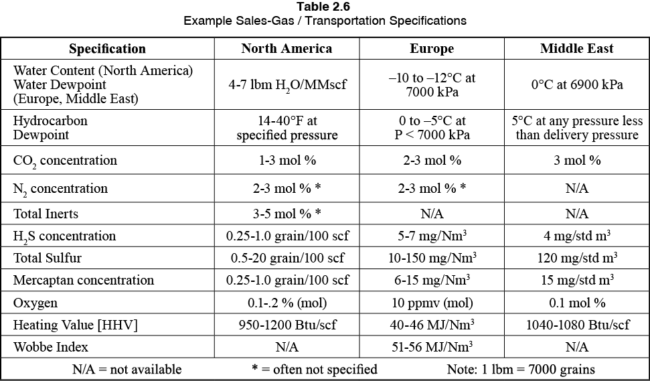
Liquid hydrocarbon products must be dry of water, and either have a vapor pressure or composition specification, along with a total sulfur specification, or a copper test.
In terms of our products, they must be safe to use, and that means that all free liquid water, or the possibility of free water condensing out in the system is eliminated. They must be safe to burn without excessive sulfur dioxide emissions (H2S and total sulfur specifications). In addition, the hydrocarbon dewpoint is important to ensure that as the gas flows through the transmission line and cools to ambient conditions to the customers that no liquid hydrocarbons can condense. This is important as these pipelines and associated end users (your water heater for example) are not designed to deal with (or burn) liquid hydrocarbons. As a result, these specifications are driven by the local ambient conditions. The warmer the climate, the more water or heavy hydrocarbons are acceptable in the sales gas stream as a result.
The gas must also meet the appropriate heating value and Wobbe number so that the customers are assured the gas will burn safely in their gas turbines (for example in power generation plants), or in your natural gas cook top at home.
STEP 4 – Select the appropriate unit operations
Now that the facility inputs (feed composition and flow rates), and outputs (sales products we want to make) the process unit operations can be selected and optimized. Let’s take a look at the options, as shown in Figure 2.
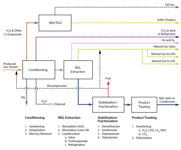
Figure 2. Example Gas Processing Facility Block Flow Diagram [2]
Gas Conditioning Options
Notice the first block in the process is Gas Conditioning. This is where the contaminant removal takes place (CO2, H2S, H2O, Hg).
Sweetening, in all intents and purposes refers to removing all acid gas contaminants (CO2 and H2S). The selection of the technology to meet the acid gas specifications depends largely on the concentration of the contaminants to be removed, and the inlet gas flow rate. Technically, carbon dioxide (CO2), is not a sour component but is often removed in the sweetening unit (amine treating).
Amine treating is the work-horse in the gas processing industry for CO2 and H2S removal, and it is always done in the processing facility BEFORE dehydration because the amine solution is generally about 50% by weight water. The gas will be saturated with water after it leaves the acid gas treating unit (AGRU) as a result.
The second step is to dehydrate the gas, i.e., remove the water content to a “safe” level depending upon either downstream processing requirements or end users.
In pipeline applications, this would require TEG dehydration. The water only needs to be removed such that was are sure that it will not condense in the sales gas pipeline.
For cryogenic processing for deep NGL extraction (-101 C, -150 F), or LNG (-160 C, -260 F) this would require molecular sieve dehydration (bone dry gas is achieved but very expensive $$). And the lastly, if we are going into cryogenic processing where aluminum components are utilized, mercury removal is critical. In large base load LNG facilities, or locations with high levels of mercury in the natural gas, there is a mercury removal bed downstream of the mole sieve dehydration units.
Gas Processing – NGL Extraction Options
Once the gas is conditioned, it then flows on to the NGL extraction block. The technology selected for the NGL extraction depends upon the operating objective of the facility and the inlet gas composition. In modern gas processing facilities, the primary NGL extraction technologies utilized are identified under item 3 below the NGL Extraction block in Figure 2:
Condensation:
JT Valve (Valve Expansion)
Mechanical Refrigeration
Turboexpander
NGL Extraction, in a nutshell, is very simple. All we are doing is cooling the gas down to get the heavy hydrocarbons to condense out of the natural gas to meet one of two criteria:
1. A hydrocarbon dewpoint specification for a sales gas stream (minimal recoveries)
2. Deep NGL extraction to upgrade the value of the products the plant can sell
The different technologies listed under condensation simply cool the conditioned feed gas stream down to a desired temperature to meet the required hydrocarbon recovery that we want to achieve.
Typical process selections for hydrocarbon dewpoint facilities would be a JT plant or mechanical refrigeration, as best case cold temperature achieved would be -40 C [-40 F].
For deep NGL extraction facilities (C2+ NGLs), a turboexpander plant is used. These plants can achieve temperatures to roughly -101 C [-150 F]. The Gas Sub-Cooled Process is the work-horse in North America in terms of our process operations, recommend that you get online and see what that process operation is about.
Stabilization / Fractionation / Product Treating
The natural gas liquids for the gas processing plant will need to be stabilized (all of the light hydrocarbons removed), so that they are safe to store and transport. These specifications can vary significantly depending upon end markets and transportation methods.
In some cases, this could be a stabilized condensate consisting of only C5+ having a vapor pressure below atmospheric conditions (example of a hydrocarbon dewpoint plant). In deep NGL extraction plants, often time the composition (C2/C3 ratio) is specified. This is important as the fractionation facilities operations will only be equipped to process an NGL stream of a composition within a given range.
The fractionation facilities consist of distillation towers that can separate the hydrocarbons essentially based upon their boiling point differences, with the light hydrocarbons going out the top of the column as the distillate products, and the heavy hydrocarbons, going out the bottom as the bottoms product.
Product Treating – Why?
Depending upon the inlet gas composition, it is common for there to be CO2 or H2S in the inlet gas that, after the gas goes through processing will not exceed the sales specification. However, these contaminants will preferentially distribute to the hydrocarbon liquid phase and can cause the ethane, propane, etc.. to not meet sulfur, CO2 specifications. It is more economical to allow the contaminants to build up in the product streams and treat the liquid product stream, rather than removing the contaminant from the inlet gas stream. The amount of liquids needing to be treated is significantly smaller (smaller equipment, lower capital cost, and lower operating cost).
There are a number of technologies than can be applied for liquid treating, and it really depends on a number of factors which is the best solution for the facility which is outside of the scope of this tip.
STEP 5 – Putting it all together – In Conclusion
I really hope that you found this tip useful. We reviewed at a very high level the issues associated with gas processing and conditioning, and the primary processing blocks that are required to go from the reservoir to market depending upon the gas composition.
So – why does my facility look the way it does? Well, it depended upon the initial forecasted feed gas composition, reservoir reserves, and production rates, combined with what the products were that they owner / operator decided was the most economic to sell based upon the local market access and infrastructure available.
To learn more about similar cases and how to minimize operational problems, we suggest attending our G2 (Overview of Gas Conditioning and Processing), G4 (Gas Conditioning and Processing), G5 (Practical Computer Simulation Applications in Gas Processing), and G6 (Gas Treating and Sulfur Recovery) courses.
Written By: Kindra Snow-McGregor, PE
REFERENCES
1. Cannon, R., “The Gas Processing Industry: Origin and Evolution”, Gas Processors Association, 1993.
2. Gas Conditioning and Processing, Volume 1: The Basics, 9th Edition, John M Campbell, Editors: Robert A. Hubbard, Kindra Snow-McGregor, 2017.
